Many people give us a call and wonder how this all works. They think we have some fancy scanner that scans in old railroad, aviation and automobile prints and spits out fancy castings. Well, we are using some pretty modern stuff, but it still is a bit of work.
First we start out with a sketch or drawing. We ask you get a drawing of the part or parts you need, or you can sketch it like you would send to a machinist. Doesn't have to be drafted, free hand will work. I have many people wanting to send me photographs with rulers in the vue. Two problems with this: One, it leaves too much to interpretation. I get responses back saying it is 'not correct', but no mention as to what is not correct. Second, I have to charge you (in this case $35 an hour) just to stare at the photographs to scale them. This is something the person wanting the casting should do, and needs to do! If you cannot do this, it is best to get someone at your site who can.
Lastly, it is best if you have a computer at home, either a Mac or a PC, that can receive e-mail. We send progress drawings via e-mail in the JPEG format. You can view them and see the progress, as well as catch any mistakes that we might have missed.
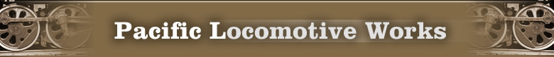
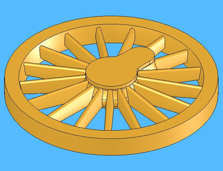
Here is the beginning of a 57" spoked wheel for an Erie Consolodation
for Theo Rehakt in New Jersey, diorama builder. The hub in this case
has a web shape, and needs to be lofted out of many small shapes.
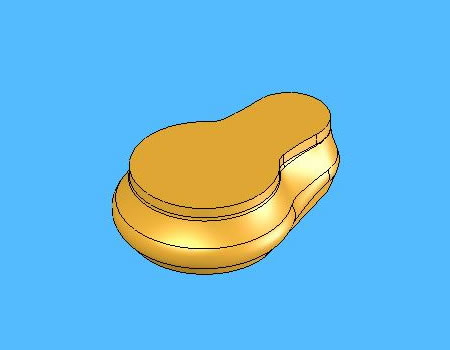
Next we add the rim, which must be positioned relative to the hub.
In real equipment, the back of the hub and the rim were almost planar.
But in O Scale, because the gauge is really a 5' gauge, we have to pull
the rim outwards a bit to get the correct gauge without making the rim
stick out so much. In this case, for a diorama, it was left scale.
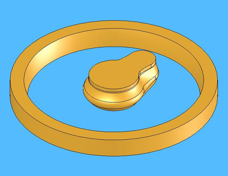
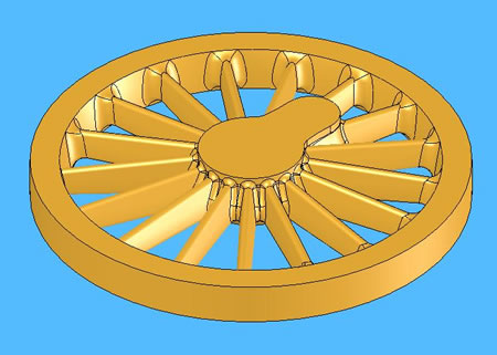
Next we need to extrude the spokes. Actually, what we do is to extrude one spoke and step and repeat it around the periphery. The spoke starts as a trapazoidal box, and then we put the profile sketches on each end and loft it into shape. The original trapazoidal box is then supressed. This gives us a nicely shaped and correct spoke. Depending on the wheel, the width of the spoke is exaggerated for additional stiffness and to allow for proper casting.
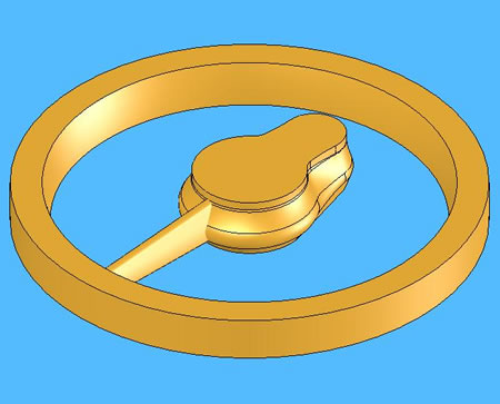
Next we step and repeat the spokes around the wheel, in this case, 17 spokes.
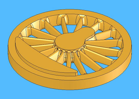
Next we begin filleting the wheel. The fillets are what really make
the wheel. Many of the older drawings have the fillet radius specified,
but sometimes they are not. In this case we make a good guess and rely
on what looks good in the end! Notice we don't fillet around where the
counterweight goes. It won't hurt anything to do so, it's just unnecessary.
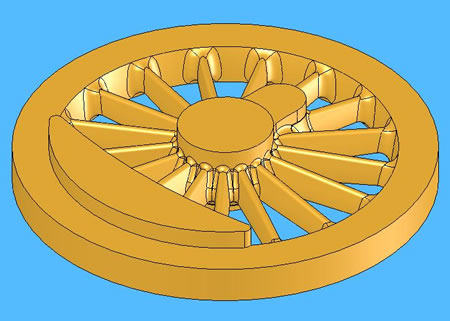
Next we extrude the counterweight. The counterweight is extruded to the height of the hub or beyond, depending on what the customer wants. In many cases, O Scale wheels have drilled holes for crank pin bolts, or pressed in studs, etc. There are endless variations, and finding one solution to fit all is difficult. We usually extend the hub and counterweight anyway such that a nice lathe cut can be taken. If the rim or counterweight has rivets on their surfaces, more attention is paid to the heights, as a cut cannot be taken without removing these features. In this case, the counterweight covers were welded on.
Lastly, we see the completed wheel. Notice there is extra material around the outside of the rim, counterweight, hub (and hub center.) You have to realize we are working with castings here, and nothing can be expected to be exact. Depending on the quality of your caster the parts can be perfect, near-perfect, warped, contain bubbles, be partial, etc. So we expect the worse from our casters, and are delighted to get anything extra. The extended hub is to relieve axial shrinkage, the counterweight extension is incase shrinkage causes a divot here. The rim needs extra material on it incase it casts out-of-round. There is also a machining spud on the backside of the hub to collet into the lathe in order to turn the rim.
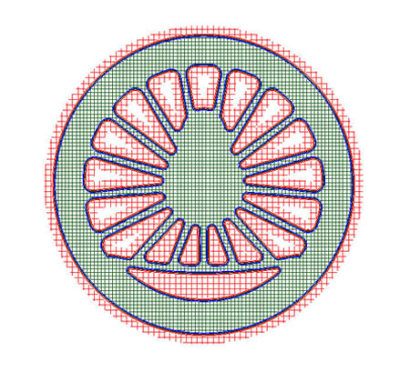
So what we have completed here is a solid model. In the computer, this part is made of brass, and is 4% larger than O Scale to allow for rubber mold shrinkage. But our stereolithography machine doesn't understand solid models. It needs a stereolithogrphy file. It just so happens most 3-D model programs can export to this format, which is a .STL format. We do that and our part is turned into a surface of small triangles.
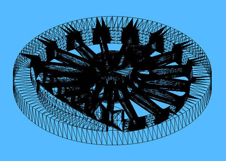
This export turns the solid into these trianglular shapes, which the
3-D printer needs. Notice the center of the wheels is almost black.
That is where most of the triangles are located. Infact, when you get
your parts back from us, you can actually see these triangles in the
casting, it is a remnant of the 3-D printing process. The finer the
triangles, the finer the surface finish. In this case, the triangles
were set to no more than 1.5 degrees, and the file size of the wheel
was still over 25MB! If the file size gets too large, our machine will
go crazy. So there is a balance that we have to achieve. We find angles
between 1.5-2 degrees give us the best models.
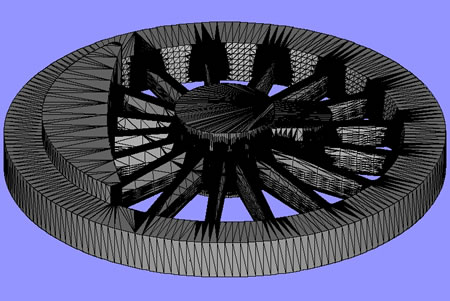
In this picture we see the triangles superimposed on the model. This JPEG was taken from a repair program we have to pass the file through. If there are any holes in the triangular surface, or a missing triangle, it drives the machine bonkers! It will want to hollow out the model on that one layer. So we have a program that examines the STL file and repairs any holes in it.
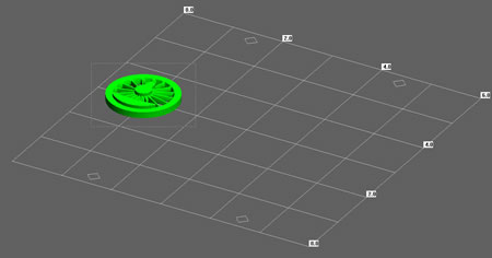
Next we import the part into the SolidScape set-up program, called ModelWorks. We see an image of the stage, and our wheel on it.
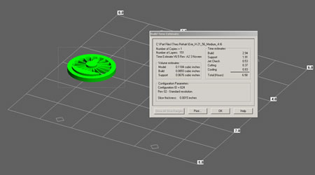
We then take and specify the slice thickness (in our case, 0.001"
backside, 0.0005" frontside.) After that, we specify how much support
we need (red wax) and let the program go off and slice-up the model.
When it is finished, it comes back with a fairly accurate time estimate,
in this case 15 hours. This model was set at 0.0015" just for the
website, so you can see if we did this for real, this time could double
or triple! From this, I can generate an accurate price for you.
Lastly, before we start, we have a viewer that reviews EACH layer the machine puts down. It's definitely not as exciting as watching the Da Vinci Code, but we have to check each layer to insure the slice program did not, indeed, go bonkers! You can see the path the jets will take in laying down the wax. Typically, parts have between 100 and 600 layers!
That's it! That's what we do just to get your part onto the machine! You can go to the 3-D Printer tab of the website to see a wheel being made.
We have told customers and groups in clinics many times, this process is not terribly expensive, but it is not free. Next time you want a model casting made, review these pages and see what needs to be done to get you from a sketch to a final brass model. It becomes easier every day, but is still a fair amount of work.